#8. ChatGPT-Powered Robot Panda
A robotic plush panda you can have a two-way convo with! Winner of the People's Choice Award at a Young Entrepreneur Pitch night. Collab project with Stan!
Helloooo AI Alchemists! ✨🤖🧪
Late last year, my friend Stan and I won the People’s Choice Award at Fishburner’s Young Entrepreneur Pitch night, where I demo’d chatting with the panda on stage in front of 200+ founders and entrepreneurs 🐼🎤
The CEO of Fishburners said:
👏🏼 People's Choice: 🦕 Becca Williams, Founder of fairylights.ai, in a landslide victory after the most captivating display of generative-AI + tech in action we've ever seen!
Together, we replaced the microcontroller with a wifi-connected Raspberry Pi and wired up the movement motors and sensors to the new board. Then we wrote code that listened through the microphone, and produced a simulated conversation using a variety of generative AI models.
Every part of this project was magical and delightful 🪄
In this post, we’ll show you how we did it, so it’s easier for you to make a talking robot plush if you want to.
Where the idea came from 💡
Within 15m of seeing this TikTok video by David from Dippaverse, where David had a conversation with a robotic plush brown bear, I had bought my own bear to do the same ✨🤯
I picked up a FurReal friends panda, which is the same brand as the original bear for $189 (AUD). You can probably find it cheaper on Ebay or somewhere like that though.
There weren’t any instructions for how to rewire and program the panda, so we had to figure it out ourselves!
How to build a talking bear? 🐼🤖🐻
Before this project, I had ZERO experience with IOT, electronics and robotics. So I am incredibly grateful that Stan agreed to help me get the panda done in 3 days ready for the pitch night. Many energy drinks were consumed 🪫🔋🔋
Here’s what we did:
🔌 Hardware steps
Locate the microcontroller in the panda.
Identify all of the hardware component inputs and outputs.
Check what kinds of signals and voltages are sent/received by each component.
Decide what pins on the Raspberry Pi should be used for each input/output and connect the hardware.
🤖 Software steps
SSH onto the Raspberry Pi
Write the software to interact with the hardware components
When the left-paw button is pressed, listen via the microphone for speech.
When the person has stopped talking, convert the speech to text.
Create a chatbot to respond to the text-based message.
Convert the generated response to speech.
Play the audio and move the head, arms and mouth while it’s playing.
🥳
🔌 Hardware steps
1. Locate the microcontroller in the panda
The first thing we did was remove the skin from the panda 😭 Then we opened up the plastic body casing to get to the microcontroller inside.
It was at this point in the process that I walked into the co-working space the next day to discover this.
The ducks decided to sacrifice the panda in a satanic ritual. Stan, Evan and Christophe witnessed the terrifying event themselves 👹🐤⛧
Step 2. Identify all of the hardware component inputs and outputs
Before we replaced the microcontroller in the panda with a WiFi-connected board, we first mapped all of the input and output components.
This helped us understand what the panda could do, so we could choose what behaviours to trigger with our own software.
Inputs: An input is something that the system uses to detect signals from a user or the outside world. They include things like sensors, switches, buttons and anything that gathers information.
Outputs: An output is something that the system does in response to the input. They include things like motors which cause movement, speakers that emit sound, switches that open or close and anything that produces a reaction.
How to map the inputs and outputs (I/Os)
To map the I/Os in the panda, we took note of where each wire connected to the microcontroller, and followed them back to the component they were attached to in the Panda itself.
Each pin on the microcontroller for the panda was labelled well enough that it was easy to figure out what each component was.
Once we identified what all the components were, we then grouped them into inputs and outputs:
Inputs
Chest Cap: Detects when the panda gets belly scritches.
Head Cap: Detects when the head is patted or brushed.
Microphone: Detects sound.
Left-Hand Switch: Detects when the left paw is pressed.
Outputs
Jaw Switch: Opens and closes the mouth .
Head Motor: Moves the head, ears and eyes into a range of different positions.
Body Motor: Raises or lowers the arms.
Speaker: Produces sound effects.
H-Wiper (Head and eye movement): Creates signals for 8 different head and eye positions.
Just because it’s pretty, this is a photo of the microcontroller that powered the original panda:
Step 3: Check what kinds of signals and voltages are sent/received by each component
After we identified all of the inputs and outputs, we then figured out the type of signal and voltages that were sent and received by each of the components.
We needed to do this to avoid damaging the hardware by wiring them up to the wrong power sources on the new board. For example, connecting a 5 volt output to a pin that can only deal with 3.5 volts could permanently break the component.
What are pins?
Pins are tiny, numbered holes on a microcontroller board where you can attach wires, sensors, modules, devices and components. They’re usually found along the outside edge or the board.
Each pin usually has a label to help identify it. On a Raspberry Pi, you might see labels like “GPIO 4” or “GPIO 17”. GPIO stands for General Purpose Input/Output pins.
What are signals?
Each pin on your Raspberry Pi board can be configured to receive input signals, or to send output signals. A signal is a message that is sent to the component connected to the board, or from the component to the board.
On a raspberry pi, there are two main signal types, digital and analog.
Digital Signals: Digital signals are like "on" or "off", or “yes” or “no” switches. You can send a digital signal to tell an LED to light up (1) or turn off (0). You can also use digital signals for button presses, where pressed = (1), and released = (0).
Analog Signals: Analog signals are more like a continuous range of messages. Instead of just "on" or "off," they can be any value in between. Think of it like a volume control on a radio that can be set to any level between silent and loud. Analog signals are often used for sensors that measure things like temperature, light, or sound.
What are voltages?
Voltage is the electrical power that is used to make your hardware components work, like turning a light on or moving a motor.
It’s really important to understand what voltage levels work best for both your board and each individual component, because using the wrong voltage can harm both the Raspberry Pi and the connected components. For example, sending a 5v current through an LED light that accepts 3.3v can blow the bulb.
On a Raspberry Pi, the standard voltage level for General Purpose Input/Output (GPIO) pins is 3.3 volts (3.3V). Different electrical components require different voltage levels to work correctly.
If one of your components needs more voltage than a pin provides, you can add in external power sources or voltage regulating components that can shift the levels.
How to check signals and voltage levels with a multimeter
The typical way to check what signals and voltage levels each component accepts, is to refer to the datasheet or manufacturing document for those components.
In this project, there was no information online about what each of the components were. So we used a Multimeter.
A multimeter is used to measure voltage, current, resistance and other electrical properties. It has two probe wires coming out of it, a black one and a red one.
To check what signals each component received, we found the pin that each component was connected to, then we connected the red (positive) probe to that signal pin, and the black (negative) probe to the ground (GND) pin on the microcontroller.
We then ran voltage through it and if the line showed a line that rose and fell like mountains and valleys, then it was an analogue signal. If the line showed a straight line that didn’t vary (usually at the top of the screen for on position or at the bottom for down position), we knew it was analogue.
To check what voltage each component had, we disconnect the wire that is supplying power through the microcontroller, with the red (positive) wire of the multimeter. Then we connect the black (negative) probe to a ground (GND) pin on the microcontroller. Then we power the microcontroller and send a signal to that pin which will run a current through it. The voltage level will be displayed on the screen.
Step 4: Decide what pins on the Raspberry Pi should be used for each input/output and connect the hardware.
After we’ve mapped the signals and voltages, it’s really easy to decide what pins should be used on the Raspberry Pi, as each pin corresponds to a different signal type.
Then, we can start transferring the hardware connections from the existing microcontroller in the panda to the Raspberry Pi!
This is what the wiring looked like before we replaced the microcontroller with the raspberry pi board:
We rushed this a bit because we had 3 days to get this ready for the pitch night demo, otherwise we would have hidden all of the connections and components inside of the panda.
🤖 Software steps
Step 5. SSH onto the raspberry pi.
The first step was to get access to the Raspberry Pi, so we could start writing code on it to control the components. We did this by remotely connecting to the Raspberry Pi by SSH-ing onto it (logging onto it from a different device).
Make sure your Raspberry Pi is powered on and connected to the same network as the device you want to SSH from.
Open a terminal on your Raspberry Pi or connect it to a monitor and keyboard.
Type the following command and press Enter:
sudo raspi-configIn the Raspberry Pi Configuration menu, go to "Interfacing Options" and select "SSH." Follow the prompts to enable SSH.
Reboot your Raspberry Pi if necessary.
Find your Raspberry Pi’s IP address by running the following command on your Raspberry Pi:
hostname -ISSH into the Raspberry Pi from your terminal computer by running:
ssh pi@<your_pi_ip>Enter the username and password when prompted, and you’re in!
You can now start writing software on your Pi as if you were writing it on your computer, MAGICAL!
Step 6: Write the software to interact with the hardware components.
These are the higher-level steps involved in making the panda appear to be moving and talking in response to a question you ask it.
When the left-paw button is pressed, listen via the microphone for speech.
When the person has stopped talking, convert the speech to text.
Create a chatbot to respond to the text-based message.
Convert the generated response to speech.
Play the audio and move the head, arms and mouth while it’s playing.
1. When the left-paw button is pressed, listen via the microphone for speech
The following code waits for the left paw button to be pressed. When it is pressed, we used the Pyaudio library to record speech through the microphone,
The following code waits for the left paw button to be pressed. When it is pressed, a method called “listen_to_message” is called, which uses the Pyaudio library to record audio from the microphone. The code records audio for 5 seconds, and then saves the audio as an MP3 file.
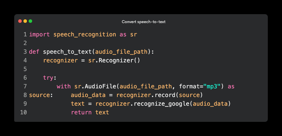
2. When the person has stopped talking, convert the speech to text
Once we have the message spoken to the panda saved as an audio file, we can convert that speech to text with the speech_recognition library.
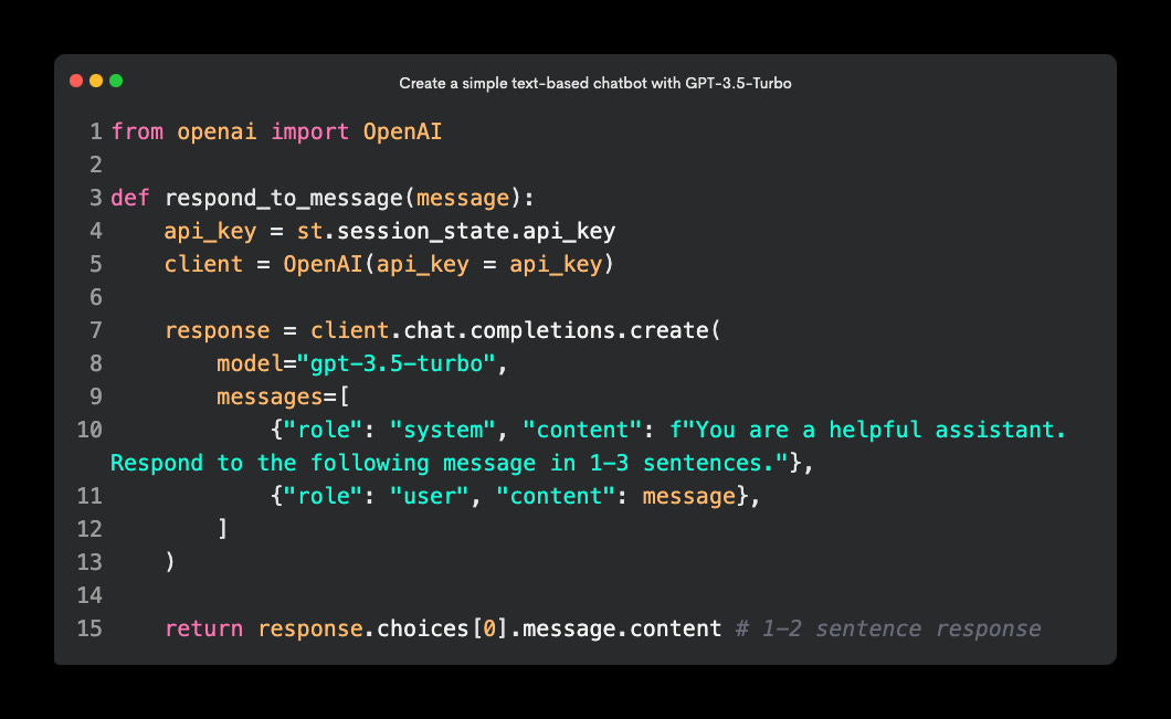
3. Create a chatbot to respond to the text-based message
Next, we need to create a simple text-based chatbot with OpenAI’s GPT-3.5-Turbo model. It accepts the text-based message we saved in the last step, and generates a 1-2 sentence response. I limited the response to 1-2 sentences so that it feels more like a real-time two-way conversation instead of a monologue.
4. Convert the generated response to speech
Once we’ve got a response back from the chatbot, we need to convert it back to audio. I used OpenAI’s TTS model to convert text to speech.
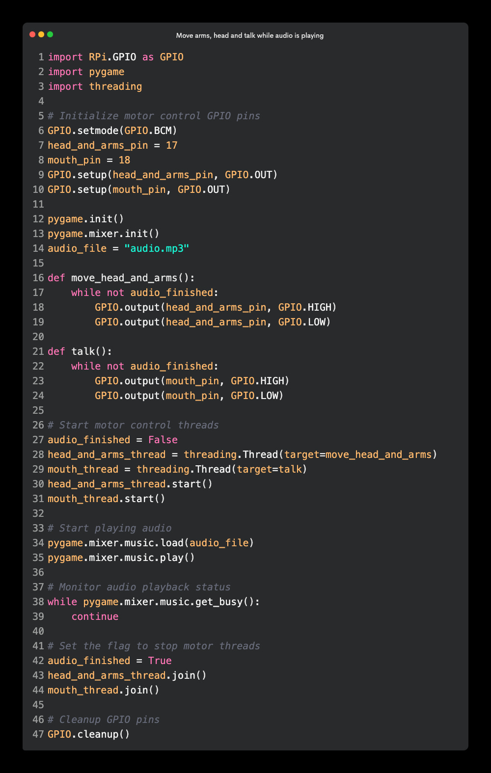
5. Play the audio and move the head, arms and mouth while it’s playing
The following code triggers the head and arm motor, and the mouth motor while the audio file is playing. This made it so that the panda moved its head, waved its arms and appeared to be talking while the audio of the chatbot response was playing. When the audio finished playing, the audio stops.
Wrap up 🌯
This talking panda that you can have a two-way conversation with was such a fun project with a huge amount of learning opportunities. We learned how to take over an existing hardware robot panda and trigger it’s physical behaviours with our own software.
We used many different generative AI building blocks to simulate a live conversation, including converting speech to text, sending that text to a chatbot to get a short text-based response, converting that text to speech again with a custom voice, and playing it through the pandas speakers.
If you want to build something like this yourself, this post should serve as a major shortcut for you, so you don’t have to learn the hard way like we did 💖


